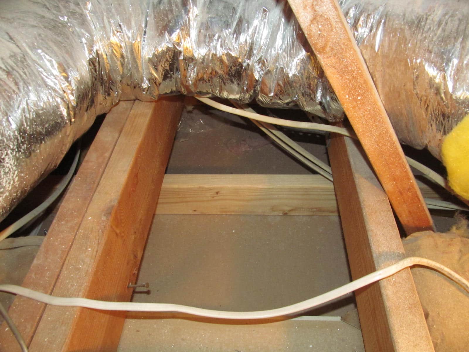
Why drill multiple small holes instead of one larger hole for wiring through floor joists, especially when guidelines exist for spacing?
4 months ago
Last Updated: August 2, 2024
Hey electricians, I came across some guidelines for drilling through floor joists for wiring. It says there’s a 2 inch no drill zone along the edges of a joist and a 6 inch no drill zone at the ends, with holes not exceeding 1/3 the joist depth. So, why would someone drill multiple half inch holes instead of one larger hole? I’m adding a new circuit in an old house and wondering how far apart the holes should be? Can anyone shed some light on this for me?
Joist thickness. 1.5/3 equals .5
??? Shouldn’t the 1.5 measurement refer to the thickness instead of the depth? For example, the depth should be 7.25″ for a 2×8 joist.
William M. nelly provided dimensions for length width depth. The width is specified as 7.25 and the depth as 1.5
No… https://buildingadvisor.com/notching-and-boring-joists/
No content
William M. nelly alright thanks for sharing this information… so essentially it’s indicating that holes should not be closer than 2 inches… I’m relieved to know this now.
Was talking about a joist that was put in place with a 7.25-inch depth.
As ‘This Old House’ suggests, it’s best to notch only the bottom 1/3 and keep wires apart to prevent overheating. Smaller holes are also easier and cheaper to firestop, especially in a duplex.
The letter is specifically for your house. Every engineer will only approve a house they were hired to inspect. In my situation, the non-union general contractor pulled off questionable practices during the addition to my parents’ house. It’s only years later that I discovered a toilet vent was actually a heal outlet. They seemed to take shortcuts rather than doing things properly.
To prevent binding and overheating, it’s better to keep the wires apart. Smaller holes are preferable to one large hole, as they cause less structural damage and weaken the joist. Make sure to have a copy of the International Building Codes, study it, and follow it diligently.
It’s rare to have so many wires on the same path that a 3” hole would be necessary. The risk of overheating with wires close together at a breaker box is also not common.
It might seem unusual, but definitely not impossible. We decided to have the service panel relocated from one end of the house to the other. Instead of completely tearing down the entire house to untangle and re-run each circuit, they simply ran the service cable from the entry point to the new panel location, and then ran feeders back to the original panel spot, connecting them to the original feeds. So, there’s a 2″ hole for the service cable and 8 3/4″ holes in a staggered layout. Some of the feeders are not shown here because I have already removed the original panel feeder and reconnected the circuit from the opposite end.
William M. nelly, that looks amazing! Great work.
The professionals did a fantastic job with that project. Well, except for the part where the panel was mistakenly installed upside down. This led to the giant supply cable running down one side, blocking access to all the knockouts. Additionally, all the bare copper ground wires had to be routed down the other side of the box in a dense cluster, to prevent contact with anything hot. It’s taken me 16 years, but I’m finally working on cleaning that mess up.
William M. nelly Yes, quite unusual. Looks like a good job there. Any lighting circuits in there? I ask because of all the 12 gauge wiring.
My old house has all old wiring, so there are numerous cables running across the basement ceiling. However, there are beams aligned with the joists at a few points, and drilling around 10″ through a beam is not feasible even if allowed. They opted to run the cables along the bottoms of the joists. In a few vulnerable areas, I’ve installed a running board to prevent the cables from hanging in mid-air (the ceiling is low, and the cables are more exposed to impact than in a higher space), but unless I’m installing a new cable, I’ve left it untouched.
None of those are just for lighting… and even if they were, this was back in early 2007 – LED bulbs and fixtures were around, but almost all the fixtures in our house used incandescent bulbs – each drawing 0.5A or more. So… if you turn on a few multi-bulb fixtures, the power consumption adds up quickly. 9 bulbs in my bathroom alone draw at least 4.5A, and when you add my wife’s 1,875W hair dryer, we’re slightly over 20A, so it’s best to have them on separate circuits in case the exhaust fan is running too. (Thankfully she doesn’t use a curling iron.)
As we slowly upgrade the house, I’m working on undoing the outdated original circuit layout and adding new ones with modern power usage in mind.
Yeah, the number of perforations is a bit worrying, but they’re located around 12″-24″ from the rim joist, and not directly under any heavy loads. From what I understand, the main stress on them at that point is longitudinal (compression/tension), and these holes are not significantly compromising in that aspect.
The key is to have no more than three wires per hole. Having more than that would mean the conductors need to be derated.