Am I correct in thinking I just need to marrette all the red wires together, the black wires together, and the grounds together at the baseboard heater location?
Hey team, could use some advice from the Electrician Brain Hive!
I’ve put in baseboard heaters before, but it’s been a minute and I really don’t want to mess this up.
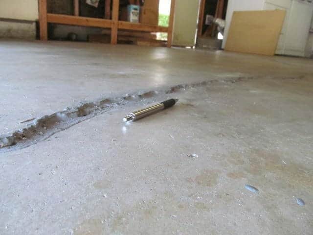
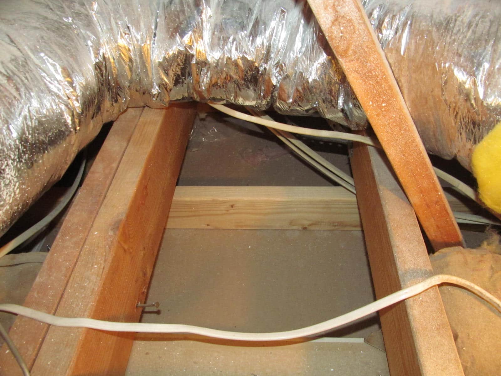
I’ve got a wire from the panel to where the baseboard heater will go, and another wire from the thermostat down to the same spot. You can spot both red wires poking out at floor level in the second pic.
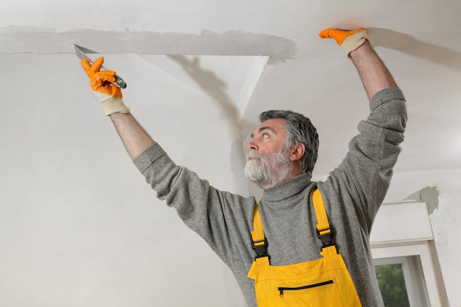
I’ve already taken care of the thermostat wiring, which you can see in the first pic.
Now, I’m just looking for confirmation that all I need to do at the baseboard heater location is connect all the red wires, all the black wires, and all the ground wires together, with one ground going to the screw.
I forgot to grab a snap of the wires at the heater itself, but there’s just one black and one red wire there.
Does my plan sound right?
That seems like a strange way to do it, but yeah, essentially you need to route the red (hot) wire from the breaker to the thermostat through the red wire, and then from the thermostat back down through the black wire, which then becomes the new ‘hot’ for the baseboard heater. I suggest using red insulation tape on the black wire going to and coming from the thermostat to make it clear that it’s being used as the hot wire.
Actually, the thermostat only has two black wires, not a red one.
Okay, so the line that is hot should be connected to the thermostat. If you made the black line hot, use that and mark the red wire from the thermostat with black tape.
Hmm…so when I connected the red and black wires to the thermostat, the instructions stated that they could go to either of the black terminals. If the red wire is hot, do I connect it to the black wire in the thermostat? This would effectively make one of the short black wires hot, which should be okay. In summary, should I connect the red wires together and the blacks together? I hope this clarifies my question a bit…
I attached labels to make it clearer….not a single wire runs from the panel to the thermostat.
No content
Yeah that’s correct – simply connect the red wire from the panel to the red wire from the thermostat to supply power to the thermostat. Next, mark the black wire labeled ‘return hot’ from the thermostat with red tape and connect it to the baseboard heater where the red/hot line is located. Also, connect the other black wire from the panel to the baseboard heater.
I’m having trouble linking the red wire from the panel to the thermostat. The wire from the panel only reaches the heater. Additionally, there is another wire running from the heater to the thermostat. I’ve included a rough sketch at the bottom illustrating the wire basics, and at the top, my proposed triangle connection.
So are you disconnecting one side of the circuit?
From the panel, one power source connects directly to the baseboard heater, while the other connects to one wire going up to the thermostat and another wire going up to the baseboard heater.
I’m leaning towards agreeing with you…. Having all the Reds linked together, as well as all the blacks…. But I’m not entirely certain. What do you mean by breaking one side of the circuit?
You should connect one end of the homerun to the thermostat and then loop it back to the heater using the other wire.
According to , if you join all the wires together, you will maintain a constant voltage of 220v throughout.
I think it’s a 220v heater, right?
Yes it is.
Just a quick question – do you have enough wire from the breaker to reach the location of the thermostat box?
Explained that the wire from the thermostat is directed towards the heater to receive power through it. That’s the approach we took when wiring the cabin.
A lot of the time you connect a feed to the box and then a single wire back to the heater. After connecting the wire at the heater, all the wiring is contained in the “thermostat” box, making sure the colors match. I personally find this method much easier.
I think we’re good on the wiring. There’s no wire from the panel to the thermostat, just from the panel to the heater and thermostat to the heater. The instructions didn’t mention anything about a wire going from the panel to the thermostat.
This is just how they wired it at my house, 240 is the correct voltage. Just keep in mind that not all thermostats require two wires.
Yes, 240.
Typically, the power line enters from the top of the box, and the feed to the baseboard heaters comes in from the bottom. For instance, if you’re considering installing a smart thermostat, some require 2 wires while others may need 3 or 4. However, in your case, you’d be fine with just 2 wires. I have a few diagrams to show you, one similar to yours but with a different wiring setup.
How about trying a smart thermostat for this?
Oh yeah, I understand how the thermostat wiring works. I just need some guidance on where the wires from the panel and thermostat connect to the heater. That’s where I’m stuck.
The diagram is incorrect in the way it is presented. If the thermostat happens to be in the off position, the heat will run continuously. If you turn the heat ‘on’, you will end up shorting out the two hot lines. It’s important not to connect them as shown in the diagram. Remy has already explained how to properly wire it – both hot wires should not be connected to the thermostat. Typically, you would run a line from the panel to the thermostat and then another down to the baseboard heater. Think of your thermostat as a simple switch that needs to be in one leg of the power supply, rather than across both legs.
I actually do not have two hot wires going to the thermostat. I have a red wire and a black wire instead.
Yes, you definitely need to pay attention to the diagram that shows a blue wire running from the panel directly to one of the black wires on the thermostat. It also indicates a red wire going from the panel to the other black wire on the thermostat, which are the two ‘hot’ lines. Each side carries 120VAC and is usually referred to as L1 and L2. There is no neutral wire included in this setup.
Sorry, I don’t have a black pen, . The dark blue lines are representing black wires in this case.
In the first diagram, you’ll notice that L1 leads to the thermostat while L2 goes directly to the heater. Picture the black and white wires in the diagram as Black and red, similar to the second diagram.
Alright, let’s begin from the start. Remove the baseboard heater for now. You’ll notice that both wires, regardless of color, go straight to the thermostat. Can you see that? If you trace the red wire, you’ll see it connects to the black wire on the top of your thermostat. The other wire from the panel connects to the black wire at the bottom of the thermostat. This causes a short circuit between both “hot” lines or L1, L2 (line 1, line 2).
Could you sketch another diagram where one of the lines goes from the panel to a wire in the heater? Your current diagram is almost there, the red line is correct as it goes from the panel to the thermostat, but the black line (which appears blue) from the thermostat should go back to the opposite side of the heater and not the red wire. If you’re having trouble understanding this, it might be best to hire an electrician. They could wire it up in about 2 minutes.
Here’s what another member, , suggested doing
Sure, as you can see, the hot line from the panel connects to one side of your heater. The red line is spliced and runs back and forth to the thermostat (even though you showed it connected to the opposite side of the heater). It’s easier to just connect red to red for simplicity. The wire returning from the thermostat now connects to the other wire at the heater. If it helps, this diagram should help. Once the wiring is complete, send us a photo before powering up the circuit.
Sounds good! I’ll wire this up in the morning and give you an update. Thanks a lot!
Actually, you’re not quite on the right track.
For the thermostat: Connect the black wire to one terminal and the red wire to the other terminal.
At the baseboard: Connect one wire from the panel directly to the baseboard. Use a wire connector to join the other wire from the panel with one of the wires going to the thermostat. Finally, connect the remaining wire going to the thermostat to the other terminal of the baseboard.
This setup ensures that one wire is always linked to the baseboard, while the other goes from the panel to the thermostat before returning to the baseboard.
I followed your instructions for the thermostat. However, I’m confused about which colors go where on the baseboard. Can you clarify? I’m a bit lost.
Hey, it’s no big deal. Both wires carry 120v, combining to make the baseboard 240v. Can you tell me the colors of the baseboard wires? Do you have any pictures of the wiring?
Just to clarify, the baseboard operates at 240 volts and has both a black and a red wire.
So, colors aren’t important. Check out the diagram I created. Orange represents the marette. Simply connect black to the black wire from the panel at the baseboard, and red to the red wire from the thermostat. Use the marette for the other two wires.
Ah, got it now! Really appreciate you taking the time to go over this with me!
Hey , no worries at all! This is something that tends to bother people – the logical order is Panel->thermostat->baseboard. The same goes for a switch and a light. However, it’s actually quite simple to switch the positions of the baseboard and thermostat in the circuit, or the switch and light. That’s how my entire house is wired. Feel free to ask if you need more assistance!
Hey , are you available?
Make sure there is no open circuit in the junction box on the baseboard heater’s 2nd end. Sometimes there are 2 wiring locations.